How the 802.1Q VLAN tag works: the first part in a series of three posts on the VLAN tagging. In this article we will look at some details on how the 802.1Q tag is constructed and how it affects Ethernet frames.
If either working with VMware vSphere or just pure networking it is almost guaranteed to use VLANs in the infrastructure. It is often useful to have a good understanding of what the 802.1Q VLAN tag actually is, where it fits in to the original frames and what headers get manipulated when using VLAN tagging.
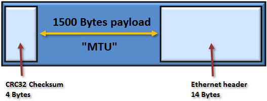
Above we see the default Ethernet frame. It has a maximum total size of 1518 bytes and any frame sent with a larger size than 1518 is be definition corrupt. That is an important fact to be aware of. Every default configured Network Interface Card and switch port must drop any frame exceeding that size.
The maximum frame size of 1518 bytes have been the same for over 25 years. For more information about the maximum possible bandwidth on Gigabit Ethernet see this article.
From the Ethernet perspective only some fields in the total packet are interesting and usable on Layer Two, i.e. readable for switches and network interface cards. At the “front” of the frame we have a 14 bytes long Ethernet header and at the very end a four bytes CRC32 checksum, called the Frame Check Sequence. This checksum is calculated and set by the NIC first sending the frame and then typically checked at every switchport at the way to the destination.
If the checksum is in any way incorrect a switch or NIC will just silently drop the frame. There are no re-sending mechanisms available at Layer 2 Ethernet. The loss of the frame will have to be detected by a Layer Four transport protocol, typically TCP, for resending of the data.
(Note that the pictures shown is not at scale.)
The Ethernet payload, that is how much data that could be carried inside the frame, is 1500 bytes and is commonly called the “Maximum Transmission Unit“, MTU.
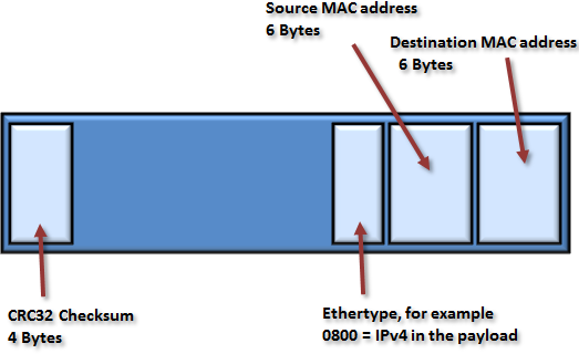
If looking a bit closer at the 14 bytes Ethernet header it is actually made up from three different fields. The first field at the very beginning of the frame is the Destination MAC address (48 bits / 6 bytes long). The destination MAC is located at the front of the frame to be very available to both switches and network cards to inspect this header and quickly begin to process this information.
After this we have the source MAC, set by the sender, and very important for switch devices. A switch will observe the Source MAC for every incoming frame to “learn” the relative location of the MAC addresses throughout the network.
The final field in the ethernet header is a two bytes information area called the Ethertype. This is used at the destination NIC to know what is carried “inside” the frame to be able to pass this on to the proper protocol above. By far is the most common protocol directly inside the frame IPv4. Standardized Ethertypes do however exists for various protocols supported by Ethernet.
In the next part of the series we will see how the Ethertype field is also changed to reflect the presence of the 802.1Q tag.
Let us now look at where the 802.1Q tag fits into this frame.
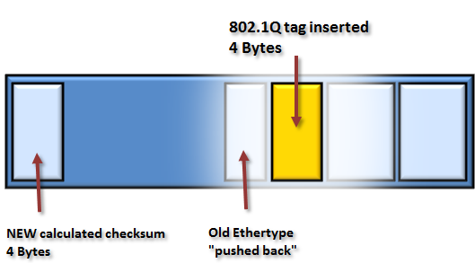
When a frame is “tagged”, either by a physical or virtual switch, an extra field of four bytes are added to the frame. An interesting detail is that the tag is not applied at either the beginning or the end of the frame but rather inserted into the packet at the 13th byte position.
The original Ethertype, indicating for example a IPv4 payload, is still present, but are moved back four bytes. (Before deliver to the end station the 802.1Q tag has to be removed and the original Ethertype put back into the correct position.)
As a “tagged” frame has been altered from its original content, including adding four new bytes and pushing the Ethertype back, the original checksum is now invalid. The switch that applied the tag must calculate a new checksum and replace the original.
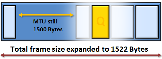
Even when the extra 4 bytes is added the MTU will remain the same, that is, the payload is still 1500 bytes. Since all original data is intact the total size of the frame does increase.
With the added 802.1Q tag the maximum frame size is 1522 bytes and as such would be seen as corrupt by all default configured switches and network adapters. To avoid tagged frames from being silently dropped at some point the network administrator must carefully make sure that switch ports where tagged frames might arrive is prepared for the larger frames and does allow processing of the 802.1Q vlan tag.
On HP switches such ports are configured as “tagged” for specific VLANs and on Cisco switches a port allowing tagged frames is called a “trunk” port. Even if the terms are used somewhat different the switches from both vendor is fully compatible with each other in transferring tagged frames.
In the next part of the VLAN series we will see some more details of what is inside the 802.1Q tag.


Nice post! This is the most understandable explanation to VLAN I’ve ever seen.
Agree with Nick…
I’ve been in the field for over 15 years and in that time I’ve read tons of technical documentation on the subject.
This is hands down the best explanation ever!
Thank you Nick and Mike, glad to hear that you liked the post.
Wonderful explaination, Thanks a lot!
Thank you for this. First VLAN explanation that makes sense.
Can we have part 2 and 3 soon, please?
is this possible if i could replace the data layer header with the vlan header on entering the switch while coming from host.
Hello,
I am afraid I do not really get your question. Could you rephrase what you wish to do?
Regards, Rickard
instead of inserting the vlan header(or tag) i.e ieee802.1Q or encapsulting i.e iner-switch link,is this possible to completly replace the data layer header with the vlan header when it need to be tagged or it is entering the switch while coming from host
Gah, you’re killing me smalls. You have two really important ‘blogs’ but stop at part 1, leaving all the juicy bits of part 2 and 3 left in the ether. PLZ PART 2 and 3! Even in 2021!
Part 2 and 3 are non existent?